Guyana Power & Light Inc. (GPL) is in the business of selling electricity to customers. We generate the power, transmit and distribute it to most of the areas along the coastal plain of Guyana. Our customer base starts all the way from Charity in Region 2 and goes up to Moleson Creek in Region 6. The islands of Leguan & Wakenaam in the Essequibo River are powered by GPL.
There are a number of commercial offices spread out across the country that enable customers to pay their bills. Customers also utilize the many services we offer with regard to the application for new service, changing ownership of service and/or request for disconnection of service.
Quality Policy
- Our organization is committed to providing our customers with a quality electric service that meets and exceeds their expectations.
- We will continually strive to improve our electric service by assessing all risks and opportunities and shall comply with all applicable Legal, Regulatory, Statutory and Industrial requirements.
- We will build and maintain mutually beneficial and rewarding relationships with all stakeholders.
- Management will ensure that all employees are trained and competent to fulfill the vision of Guyana Power and Light Inc.
Power Generation
The principles of electricity were discovered by the U.K. scientist name Michael Faraday between the years 1820 and 1840. Subsequently, a machine called a Generator was constructed to produce electric energy in bulk. The generator is an electromechanical device which converts mechanical energy to electrical energy. Even up to today Michael Faraday principles still applies with the generator, thus to generate energy three conditions must be met: 1. Must have a conductor. 2. Must be a magnetic field. 3. Must be relative motion between the conductor and the magnetic field. This exercise seeks to briefly explain how Guyana Power & Light Inc., (GPL) electrical energy is produced, distributed and transmitted. Note that at the generating source of GPL the configuration of the system is three phase four wire star.
 How Power is Generated
In GPL the electric energy consumers used daily are generated from Alternator Machines (generators) which are rotated by fuel oil, namely Light & Heavy Fuel Oil combustible engines called the Prime Mover. The engine is coupled to the alternator and the engine shaft in turn rotates the alternator shaft which is called a Rotor. The rotor is an electromagnet which is supply with a direct current (d.c.) source. This current is called Excitation Current and the source is called an Exciter. The exciter is also coupled to the alternator from the non driving end of the complete machine. Exciters are classified according to the manner in which the rotor is supplied with excitation current. In GPL the rotor current is supplied with current from an external source, so the direct current machine is said to be a Separately Excited Generator. The exciter with the use of automatic motor control systems supplies the rotor with a d.c. current via slip rings and brush gear thus energizing the coils in the rotor. The varying of the rotor current setup a Generator Flux or Magnetic Field in the alternator. Thus magnitude of the current varies with the magnetic flux density. Hence, the rotation of the engine shaft caused the magnetic field to rotate providing the relative motion. Note on a practical stand point, this relative motion creates a condition called Electromagnetic Induction. This induction is achieved by: 1. The magnetic field being stationary and conductors moving through it. 2. The conductors stationary and the magnetic field moving past the conductors. GPL use the latter of the two and the stationary conductors are in the form of bars consisting of three set of windings which are called the Stator Bars (armature). All conditions being met with the relative motion and the field current being varied in the generator a Magnetic Circuit is setup which consist of the electromagnetic (rotor), air gap (the very narrow space between rotor and stator) and the armature. When the magnetic lines of force of the field are cut voltage is induced in the stator windings and with a close loop electric circuit in place this further creating current to flow through the stator windings. The magnitude of the induced voltage is given by the following expression:
e (volts) = B×L× ν×Sinθ where
B is magnitude flux density in Teslas.
L is the length of the conductor in the magnetic field in metres.
>Θ is the angle that the direction of travel of the conductor makes with a line that is perpendicular to the magnetic field at any given time.
ν is the relative velocity in metre per second.
 Thus varying any component will either increase or decrease the magnitude of the voltage induced in the stator. After the voltage is induced in the windings, the alternator is so design that four conductors are brought out of the alternator. One of the conductors is called the Neutral Terminal and this conductor is form by connecting one end of each of the coils of the same polarity in the stator windings together. This conductor is terminated to earth using various methods. The other ends of the coils in the stator windings are brought out as three conductors of different phases namely, Red, Yellow and Blue. These three conductors in GPL case are connected to the Bus Bars located in the Switchgear Apparatus which is housed in the Stations. From the Station the power and or current is utilized via circuits connecting to the bus bar for transmission and distribution.
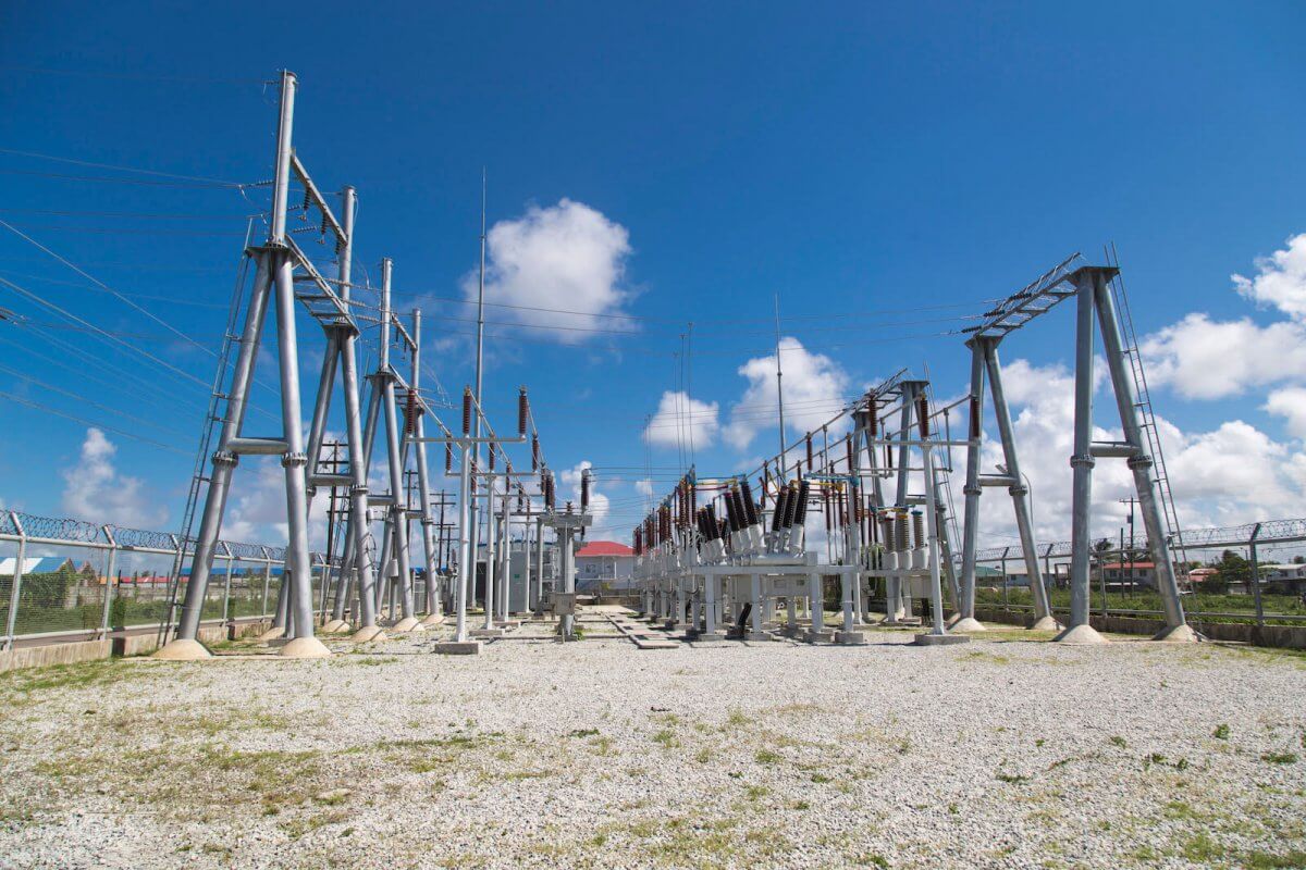
Distribution of Power to Consumers
Circuits are connected to the bus bar in the switchgear apparatus and distribute via Distribution Power Lines at 11KV and 13.8 KV. This is also called the Primary Distribution Voltage and these circuits are routed to the areas which can be called the Load Centres. At the load centre the voltage is breakdown to a usable level by a machine called the Step-down Transformer, the step-down voltages are namely 120, 240 and 480 volts for the consumers to utilize. At this usable level the electricity is routed in the area via network of wire called the Secondary Mains and at the consumer’s home a Service Line is connected from the secondary mains to the consumer home.
Transmission of Electric Power
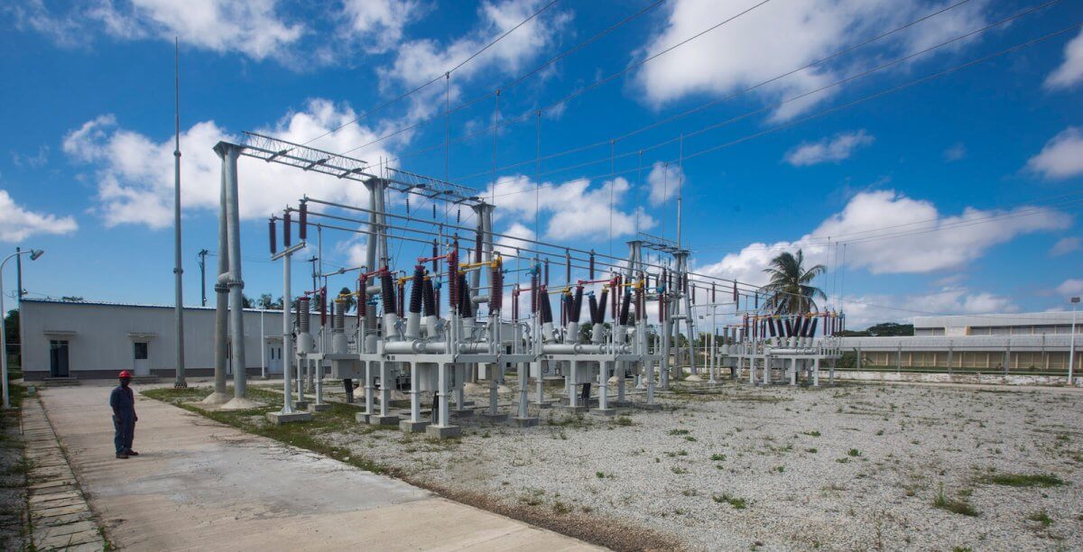 The transmission lines served to link and transfer bulk electric energy between Power Stations thereby creating an Interconnected System. Thus transmission lines operating voltages are generally 33KV, 69KV, 110KV, etc. Thus, the complete interconnected System consists of the Generating Stations, Transformers, Transmission & Distribution Lines, Secondary Mains, Service Lines and the Consumers. This system is called the National Grid. Currently in GPL the transmission voltage is 69KV and this network is used also to transfer electric energy to load centres at very high voltage. In doing this the electric energy need to be transfered economically and to achieve this GPL uses a machine called the Step-up Transformer. The reason for transmitting a high voltage is proportionately reduce the current in the conductor, thus keeping the power transmitted nearly equal to the power input. At the load centres the electric energy is delivered to the consumers via the distribution lines.